Starting HKL-2000
The installer places an HKL-2000 icon (Figure 11) on the desktop that will launch the program. The icon will set important environmental variables and launch a terminal window that will display HKL-2000's runtime information.

Figure 11. The HKL-2000 Start Icon
You may start HKL-2000 from a terminal if you wish. If the HKL-2000 suite has been installed in the default location (/usr/local) you can typically just type HKL2000. The HKL-2000 suite must be configured for your system, and a license key must be installed before it can be run. Installation and configuration of the suite are described in the Appendix. You must have permission to write files in the directory you start HKL-2000 because the program writes several files to the working directory.
Site Definitions
To work with diffraction data, HKL needs to know details about the experimental setup. This information is stored as a data collection "site". Therefore, the first dialog to appear asks you to choose a site definition (detector and other site information) from the menu (Figure 12). You must select a site definition (or use the Site included option) before continuing to the program.
A site definition contains information about the experimental setup, such as the X-ray detector, goniostat, and X-ray source. The definition includes the detector name and type, the axes of rotation and misalignment parameters of the goniostat, the X-ray beam properties, and properties of the diffraction image files collected, especially the expected suffix for these files (e.g., *.img, *.osc, etc.). It contains the X and Y coordinates of the direct beam position on the detector, which are crucial pieces of information. The site files are traditionally stored in /usr/local/hklint but can be placed in any directory if the environmental variable $HKLDIR is set. If your installation of HKL-2000 was created using the installation program, then the icon it creates will automatically set this variable. This directory will contain one subdirectory for each site. Each site definition directory contains a "site file" called def.site where most of the settings are stored. These subdirectories may also contain other files such as detector calibration data (in the form of files called def.cal and denzo_nonunf) which are necessary for processing uncalibrated data. For synchrotron data processing, these files should be obtained from the synchrotron beamline.
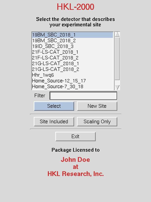
Figure 12. The HKL-2000 launch and site selection screen.
The Site Included option
The site included option tells HKL-2000 to use a def.site that is located in the same directory as the data. This option can be convenient when sharing data or downloading data from ProteinDiffraction.org.
Creating a new site
To make a new site, click
on the new site button. A new window with a field to give the new site
name will open. This will create a new subdirectory in /usr/local/hklint or $HKLINT
with the name you give (note that the user running the program will have to
have permission to write to this directory). It's
best to use a descriptive name that does not contain spaces. It can be
helpful if the name indicates a time period, like home_Raxis_fall_2018
or 19-ID_2018_run3 (Figure 13). Now click on the detector type button, and select
your detector. Some detector manufacturers have different models, and these are
listed under each general detector heading. If your detector is not listed at
all (unlikely, but theoretically possible), you will have to contact HKL
Research (or your beamline coordinator) for the appropriate site file.
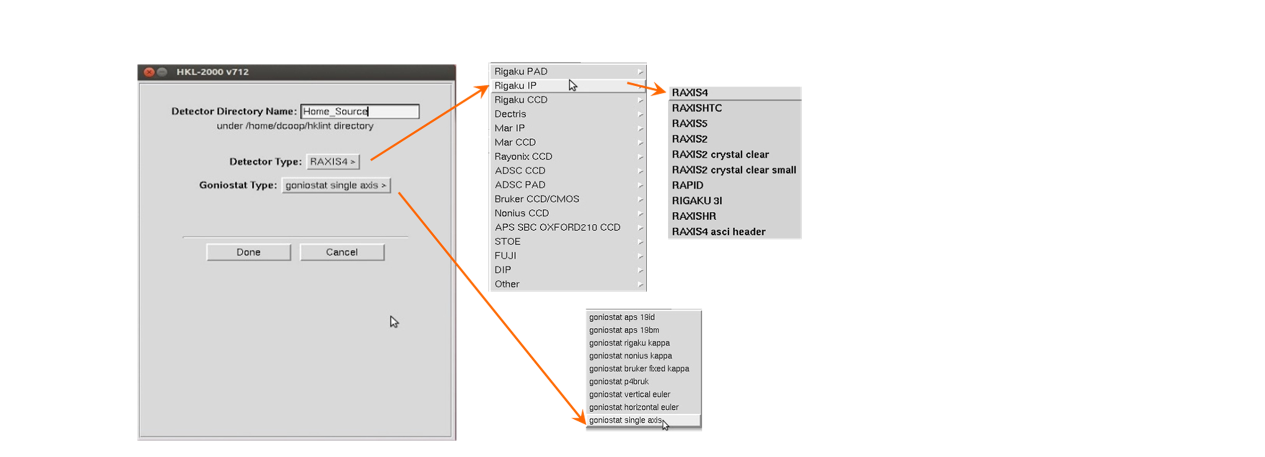
Figure 13. The "New Site" selection pane.
The most important values in the site file are the X-beam and Y-beam positions and goniostat type. Be sure to record them every time you collect data because they can fluctuate. The default values for newly created def.site files will almost always have incorrect values! You can change these by clicking on Site Configuration (see below) and make changes using the dialog. While not recommended, it is also possible to edit the appropriate line in the def.site file in the newly created subdirectory and then restart the program. Collecting and processing data with a well-characterized crystal (such as lysozyme) can ensure you are using a correct site definition.
Choose the appropriate goniostat type from the predefined list. Presently the following types of goniostats are available:
- single-axis - most common
- vertical euler - goniostat used with Rigaku Rapid, Saturn and Raxis HTC detector>
- horizontal euler
- nonius kappa - goniostat used by Nonius KappaCCD and Kappa2000 systems
- rigaku kappa
- bruker fixed kappa - used with Smart 1000 and Smart 6000 Bruker systems
- p4bruk - P4 goniostat used with Smart 6000
Once you've selected the correct detector and goniostat, click OK. The new site definition directory will be created with the appropriate files, including a def.site file. You will now get the main HKL‑2000 window.
Make sure the site file is correct! Click on Site Configuration on the top menu bar, and this will bring up a window with the site parameters (Figure 14 and Figure 15 ). You can verify that the detector is the right one, and you can specify important parameters like the X Beam and Y Beam Positions and the Wavelength and so on.
Features of the site creation dialog:
1. You can load in data from an existing site file by clicking on the load site info button. This brings up a file navigation window where you can choose a site file (def.site). This is very useful for just changing the beam position.
2. The anode type (and thus the wavelength) for rotating anode X-ray sources is specified in this window, while the wavelength for synchrotron X-rays is specified by data set in the main HKL‑2000 window (and is hopefully, but not guaranteed, to be correctly specified in the image file header -- check to make sure!).
3. Clicking on save site info means that you are permanently editing or updating the file called def.site (in /usr/local/hklint/sitewhatever). For this you will need a password (which is provided to the Contact Person your group has specified with HKL Research). This is not a typical user option. Also, the user running the program must have permission to write to the directory that contains the site file (usually /usr/local/hklint/sitewhatever).
4. You can use your updated site parameters without saving them to the def.site file by clicking the close button. The altered site parameters will remain in effect until you quit the program, after which time they will revert to the original values.
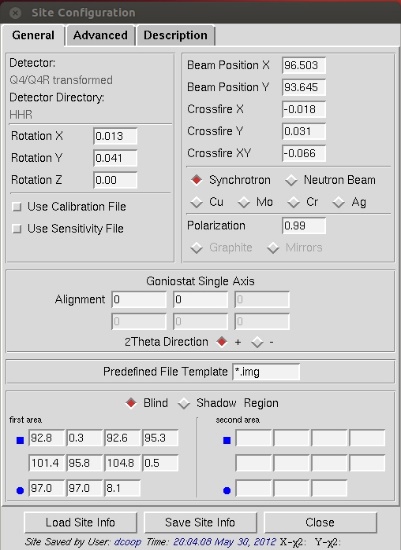
Figure 14. The main dialog for site creation.
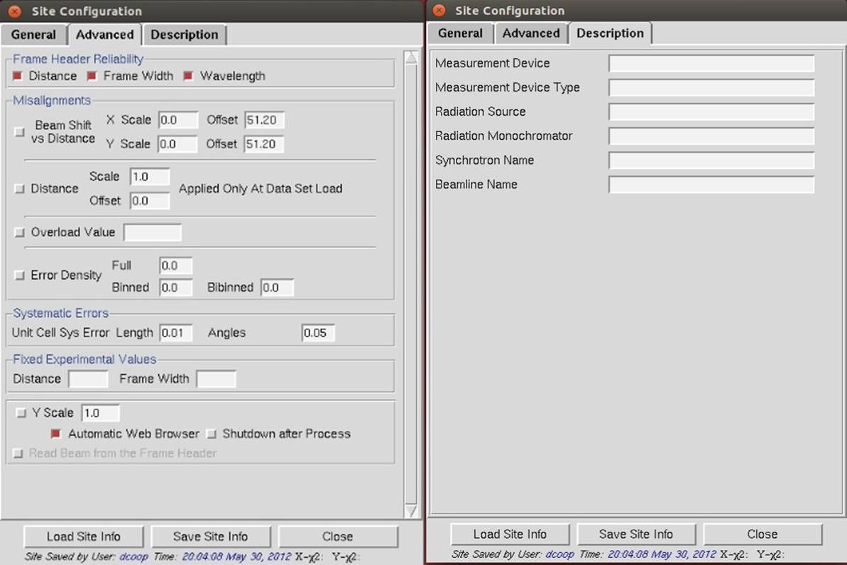
Figure 15. The Advanced and Description tabs of the site configuration window.