|
HKL-2000 Online Manual |
||
|
Previous Installing and Starting |
Table of Contents | |
Data, Results, and Datasets
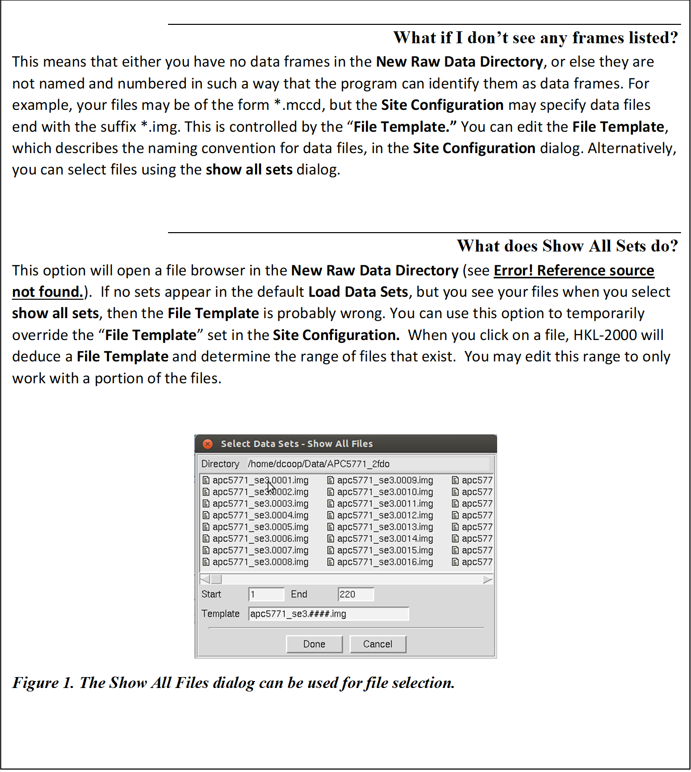
Select your data files using the Directory Tree and the New Raw Data Directory field.
The Directory Tree Window
Double clicking on a file folder displays the subdirectory contents of that directory. It will not display the files in that directory, so don't be puzzled when you can't see your data files. To go up one or more directories, double click on a parent directory. To make a new subdirectory, single click on the folder under which you want to create a new directory, click on create directory and a dialog box will open with the path displayed. Append your subdirectory name onto the end of this path and click create. If your data is in a directory configured to auto mount but is not currently mounted, click amd access (auto mount directory), type the name of the directory and click access to mount (Figure 16).
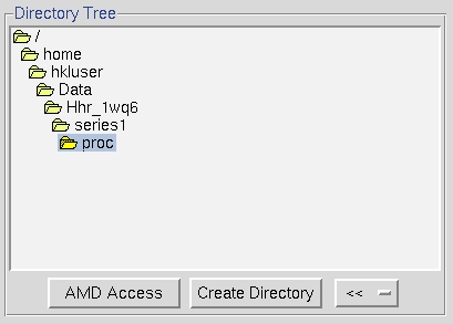
Figure 16. The directory tree
Select the raw data directory
Single click the subdirectory that contains your data (which will highlight it), then click the ">>" button to the right under New Raw Data Directory. The full path will be written in the field next to the >> button (Figure 17).
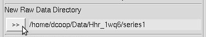
Figure 17. The Raw Data directory
Choose an output file directory
Select a directory for your output files using the Directory Tree and New Output Data Directory (Figure 18). The suggested convention is to have a subdirectory for your output (historically called proc) in the directory that holds your frames. The nice thing about having proc subdirectories is that if you reprocess the data multiple times (say, in different space groups) you can have a different proc directory for each attempt (e.g., proc_home, proc_p222, proc_p21, proc_p6, etc.) and not worry about overwriting your work or having to make new file name patterns.
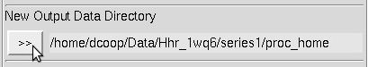
Figure 18. The Output Data directory
To make a new subdirectory, single click on the folder under which you want to create a new directory, click on create directory and a dialog box will open with the path displayed (Figure 19). Append your subdirectory name onto the end of this path and click create. This will create the directory and select it in the directory tree. A shortcut button Create proc will create a directory named "proc" (the traditionally named processing directory) in the selected directory.
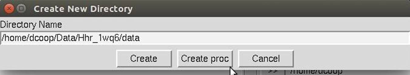
Figure 19. The Create New Directory dialog
The double arrow button (<<) can be used to create a shortcut to a directory to facilitate quickly selecting a directory. This may be useful if you have to select multiple data sets that are in various places. To add a shortcut, click the add button. To switch to one of the shortcuts, select the shortcut from the list.
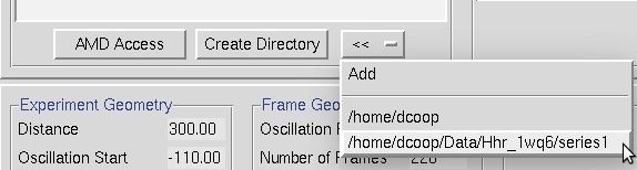
Figure 20. The << button can make directory shortcuts.

Selecting datasets

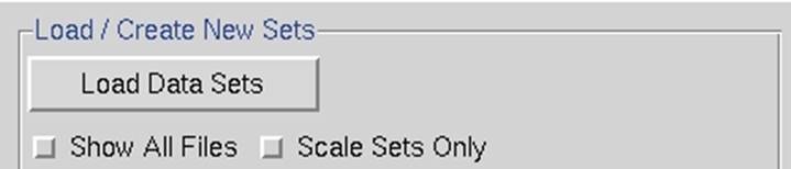
Figure 21. The Load/Create New Sets window
If you have not clicked on one of the checkboxes below the load data sets button, you should see what the program considers to be the sets of data frames in the New Raw Data Directory, with # signs standing for digits of the frame numbers (Figure 22). Single click on the set of frames you want to process - it will turn blue - then hit OK. The Select All button has been added for convenience.
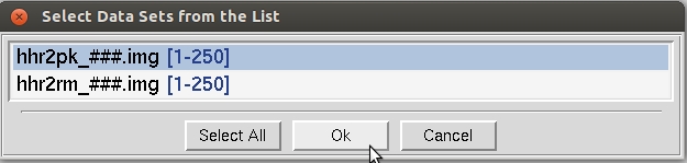
Figure 22. The Load Data Sets window
When the set has been added, a blue box will appear in the main window summarizing the properties of the set of frames you have added (Figure 23). Once you have loaded the different sets of data, the select button at the bottom left of the set box allows you to see more details about the set or manipulate the set.
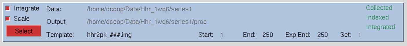
Figure 23. The Single Set window
Removing sets
If you would like to remove a set, click the select button of the set you want to remove. Then click remove set in the Set Controls panel on the right side of the main window. The program will ask if you really want to do this, and if so, the set will be removed.
Integrate, Scale, and Collect Checkboxes
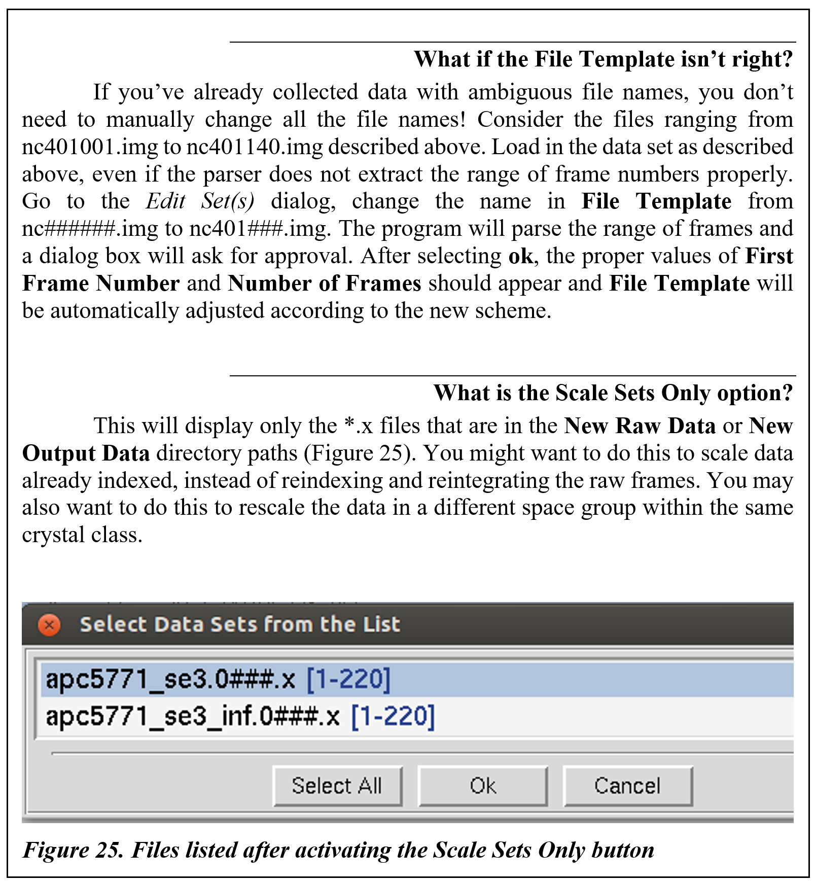
The checkboxes on the left of the data set window tell the program what you want to do with the data in this set. Most installations of HKL-2000 will have checkboxes to index and integrate the frames (integrate) and scale the data (scale). Some installations will also have a checkbox to collect the data (collect). The default is for all the available options to be selected when the set panel is displayed. Control of data collection using HKL-2000 is currently only supported at the Structural Biology Center (SBC-CAT) beamlines at APS and for a few selected detectors. If your configuration of HKL-2000 does not support direct data collection, the collect checkbox may be missing. If you want to scale frames that have already been indexed and integrated, just unselect the INTEGRATE checkbox, but leave the scale checkbox selected, and the program will know that you are passing that data set directly to Scalepack. If you are working with data from more than one wavelength, you can select integrate for all the sets, but you have to scale the sets independently. Integrating all the sets at once will ensure that they have the same crystal orientation parameters.
![Working with multiple data sets
You can load multiple sets of data within the SELECT data window. Clicking once selects, clicking again deselects. You do not have to hold down any additional keys to select more than one � just click on each set you want.
Selecting multiple sets is extremely useful when you have collected multiple data sets from a single crystal and want to index and process them all together. Examples of this include:
1. multi-wavelength experiments,
2. inverse-beam experiments,
3. data sets which differ by the 2q offset of the detector, or
4. low-pass and high-pass data sets that differ in the crystal-to-detector distance.
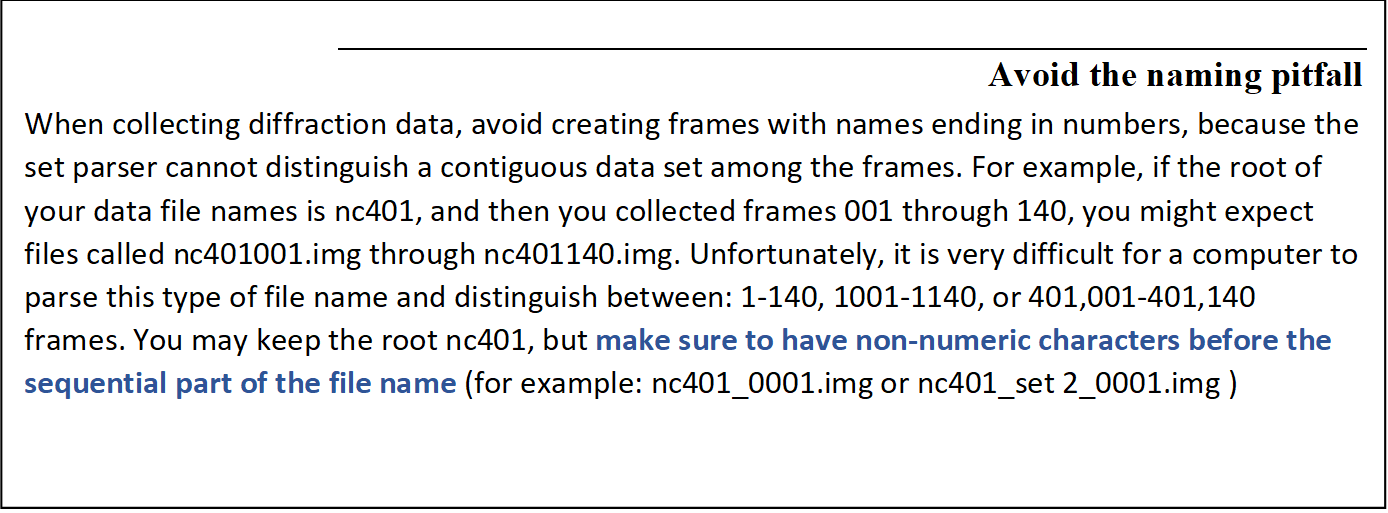
In all cases, if the goniostat is aligned (and this alignment is described in the site configuration [def.site file]), the crystal has not been moved relative to the goniostat, and the header information of the image files is reasonably accurate (so that detector distance and position information is present), then you should be able to process all of the frames together from a single auto-indexing. This will ensure that the indexing from all sets is consistent.](Images/4-image014.png)
Splitting sets
Notice that under the panel called Set Controls, there is an option called split set. This splits your data set into two or more groups, which can then be integrated consecutively, independently, or selectively. One reason to do this is if you had a bad or blank frame somewhere in the series of frames. Additionally, when screening crystals, you may have two orthogonal images which results in non-consecutive images with consecutive file numbers. In general, sets are split whenever there is an interruption in a contiguous series of data collection. To split a set, select the desired set and then click on the split set button in the Set Controls panel. A new box will appear that has two sliders (Figure 26). Move the top slider to define the end of the first set, and then move the bottom slider to define the start of the second set. If you want to skip one or more frames, just make sure that they are in the "gap" between the two sets. When done, click on the split button, and a new set will appear (Figure 27). Make sure that the Distance and Oscillation Start values are correct for each set (they should be read from the header of the data files, but you never know).
In principle, you can split a data set as many times as you need to; however, keep in mind that 3D integration cannot work across the boundaries between split sets.
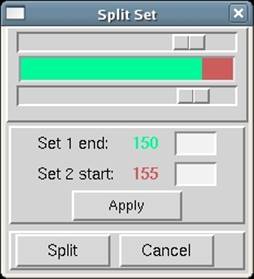
Figure 26. The Split Set window
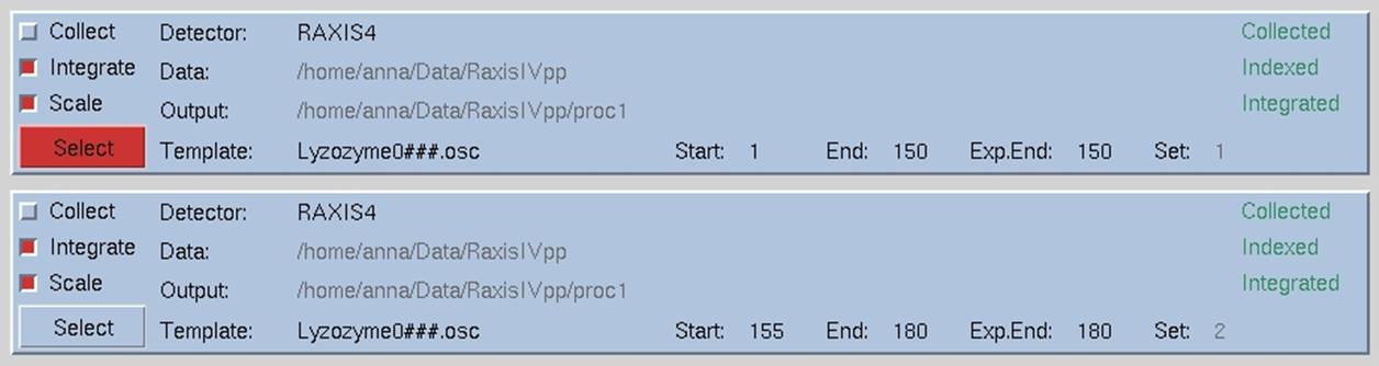
Figure 27. Data set divided into two sets removing four images in the middle.
Checking and Editing Sets
When you select each data set, the program will display the set's parameters at the bottom of the window under Experiment Geometry, Frame Geometry, Exposure Time and Options information panels. Make sure the parameters for each set are correct. These values are taken from the image's header, but the header is not always correct. Changes can be made in the Summary tab or the Edit Sets dialog, both described below. There are three ways you can do this. The quickest method to see the parameters is to look at the experimental details at the bottom of the Data tab (Figure 28). This information will correspond to the "selected" set. The information in this frame is not editable.
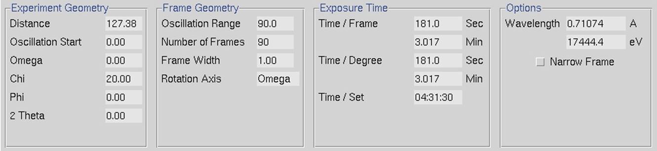
Figure 28. The experimental details panel
The second way that you can view set parameters is to switch to the Summary tab (Figure 29). The information in this tab is editable. The View Controls panel is beneath the sets you have and allows you to select the information you want to be displayed in the panel at the top.
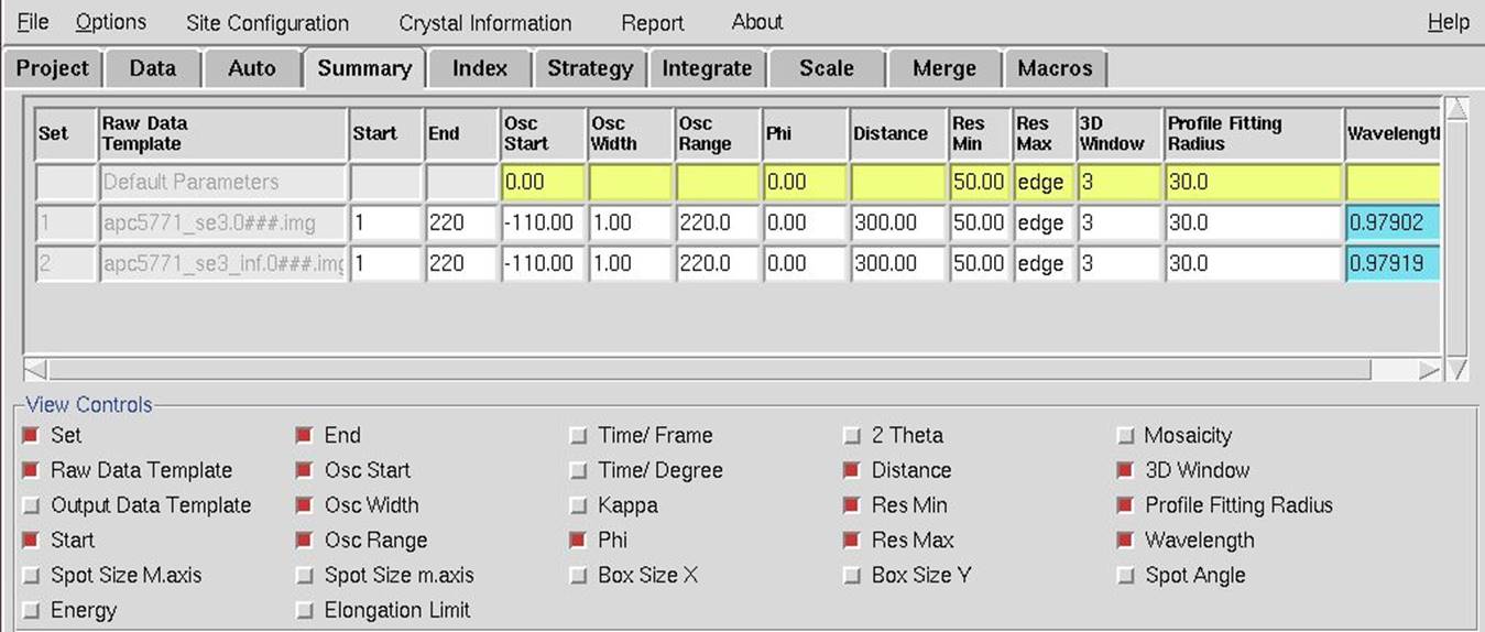
Figure 29. The Summary tab showing two datasets
The third way in see the experimental details of your sets is the Edit Sets dialog in the Data tab. The edit sets button (Figure 30) will bring up a dialog with a different tab for each set of data (Figure 31). If you edit information about the sets, click done to save the information. Use the cancel button if you have made changes but do not want the information saved.
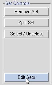
Figure 30. The Edit Sets button is in the Set Controls box
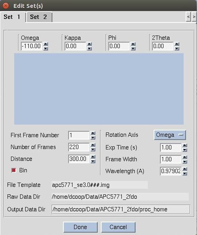
Figure 31. The Edit Sets dialog
Start working before all frames are collected
You don't have to wait until you have all the frames to get started processing your data, which can be useful if you are processing data as it is being collected or transferred to your computer. In the Edit Set(s) window, enter the correct Number of Frames you are planning to process in this batch. You will notice that as you enter this number, the Number of Frames value will increase in the Frame Geometry window, as well as the Exp. End in select panel at the top of the page. Notice as well that the End value in these two fields does not change -- this is the number of frames that the program knows is on hand at the moment. For example, suppose you are collecting 100 frames of data, and you have 20 collected so far. You would enter 100 in the Number of Frames box before you started the integration of the 20 frames collected so far. You could then start the integration job, and the first 20 frames will be integrated. When the last frame on hand is processed, the program will wait -- giving the message "Waiting for Frames" -- and when the new frames are written to disk, the program will continue to process them. This is especially helpful at places like synchrotrons, where the frame integration rate is a substantial fraction of the data collection rate, and you want to maximize your efficiency.
Another way you can use the Number of Frames value is to stop the integration before all the frames are processed. This is helpful if you have a lot of frames that have lots of spots and so take a long time to integrate. Perhaps you just want to process a wedge of this data and get some idea of its quality. For example, say you have 300 frames but just want to look at the first 30. Enter 30 in the Number of Frames box and start processing. The first 30 frames will be integrated, and then the program will stop. This is easier than splitting the data set and more civilized and nicer than hitting the abort button.
|
HKL-2000 Online Manual |
||
|
Previous Installing and Starting |
Table of Contents | |