|
HKL-2000 Online Manual |
||
|
Previous Display Data and Peak Search |
Table of Contents | |
Auto-Indexing
Before you can index diffraction data properly, you first have to characterize the underlying symmetry of the crystal. HKL will attempt to index the data within each Bravais Lattice type. For historical reasons, the process indexing the data in all crystal classes is known as auto-indexing. To auto-index your data, select the Index tab of the main HKL-2000 window. If you have more than one set of data, they will appear in the Pending Sets window. Select the one you used for indexing. You may also want to change the Resolution Limits (the default is to the edge; changing it later is also OK), then index the data by clicking the index button. The program will try to fit the diffraction pattern in each of the 14 Bravais lattices and generate an index describing the fit of each lattice to the observed peaks. The Bravais Lattice dialog will automatically open to allow you to select a different lattice. If you are working with unfamiliar crystals, it is a good idea to refine some parameters in the primitive triclinic lattice (space group P1) and revisit this dialog later. Close the Bravais Lattice window using the apply and close button. Check to make sure the green circles identified by indexing line up with real spots by examining the Image Display window (click the display button if it's not already open). You can toggle the predicted spots on and off using the update pred button.
The Pending Sets window
All of the data sets that you are integrating will appear in the Pending Sets box in the upper left corner of the Index page. Which sets are present is controlled by selecting the Integrate checkbox for each data set on the Data tab. You can choose a particular set to index and/or refine by selecting it, which will highlight it with a blue background (Figure 51). Once you have selected a set, you can change the parameters of the integration for that set, while leaving the parameters for the other set(s) unchanged. For example, set 1 may be set for processing to 3 Å resolution, while you may want to process set 2 to 1.5 Å. Similarly, perhaps the Spot Size is 0.3 for the first set, but 0.25 for the second set. Perhaps the 3D Window is five frames for the first set but only 3 for the second. The Pending Sets box allows you to toggle between the pending data sets in preparation for integrating them in the same run. You can also accomplish the same thing by going to the Summary tab page and editing the parameters for each set (Figure 52). It is worth noting that if your datasets are from the same crystal, with approximately the same orientation, you can probably integrate all of the data at the same time. You only need to index one of the pending sets before integrating them all. It is wise to keep an eye on reflection markings during integrations. A sudden increase of rejected and/or unpredicted reflections after the transition to another set, then you may have to index, refine, and integrate the sets individually.
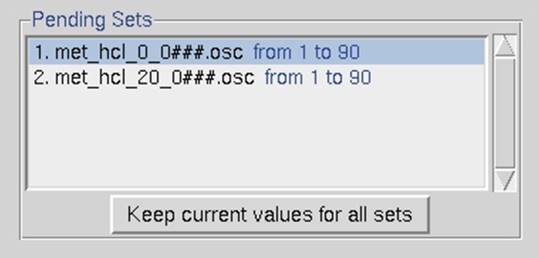
Figure 51. The Pending Sets box
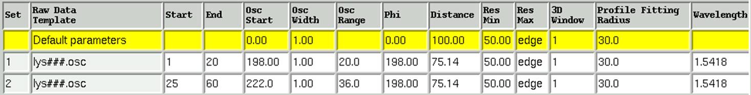
Figure 52. The summary information about processed sets
Initial Parameters for Indexing
Most of the default setting are sufficient for indexing, and there are only a few that you may want to consider before indexing your data. If your data looks good close to the edge of the plate, then leave the default settings as they are (Figure 53). However, there are certain situations where it may be appropriate to change the Resolution. For example, if your data does not extend to the edge of the detector, or if your data has a combination of weak reflections and ice rings you may want to limit (by raising) the resolution. For example, if you have an ice ring, try setting the Max value to 4 Å. If you have a secondary lattice which is more pronounced at higher resolutions, try indexing at low resolution. For your convenience, a Limit Resolution in Pre-refinement option will limit the resolution to 4 Å for the initial pass at indexing before extending the resolution to the resolution limit you have set. This can help with ice rings or weak resolution data. Do not truncate your resolution pre-maturely, however. HKL can detect reflections that your eyes may not. Additionally, you can truncate your data at the scaling step.
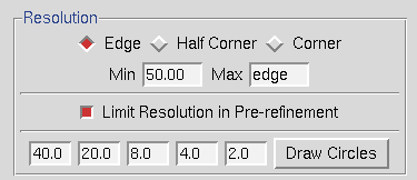
Figure 53. The Resolution limits box
Other parameters you may want to change before indexing are at the top of the Controls box (Figure 54). If you have a well-diffracting crystal with a large unit cell, you may want to increase the number of reflections that are used for indexing. The Sigma Cutoff Index limits the signal to noise ratio that is used for indexing. If a secondary lattice is present, you may want to increase this. On the other hand, if your data is very weak, you may need to decrease the limit.
The index button starts the auto-indexing process and will attempt to index the data in every crystal system.

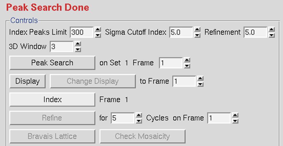
Figure 54. Other pre-indexing options.
Peaks used for autoindexing
The green circles that appear during indexing denote the subset of the peak search peaks that were used in the auto-indexing. The criteria for usability include falling within the resolution limits specified, high enough signal to noise, sufficiently low background (which helps to eliminate spots in ice rings and overlaps), and identification of a lune. If there aren't any green circles after auto-indexing, one or more of the following problems may be the cause:
1. The Peak Search was done on a different frame from that being used to auto-index. In this case, you should have already gotten the error message "Error -- Peaks none." The remedy is to make sure these are the same. The rightmost column of the file peaks.file, generated during peak searching, tells which frame the peak search peaks were derived from.
2. None of the spots are strong enough to qualify for use in the auto-indexing routine. The remedy is to take a longer exposure, pick more peaks on the frame or on several frames, or lower the Refinement Sigma Cutoff, which is normally set at five σ. Lowering the sigma cutoff is a dangerous option, however, and is not recommended because weak reflections are not high-quality reflections, and therefore may be noise.
Denzo assesses the quality of the background of each spot against criteria for slope and uniformity, and if a certain fraction of the pixels in the background fails the test, then the whole spot is rejected. This is controlled by the keyword reject fraction, which can be [DRC1] entered in the Macros Tab. This default value for this rejection is 0.75, i.e., the 75% of the background pixels must be acceptable. If you have an ice ring, you can increase reject fraction until most of the spots in the ice ring are no longer picked up. Useful increments are 1-2% at a time. Do this while you are looking at the display, just as you would do for spot shape and mosaicity.
3. No lunes could be detected. This can result from either too many or too few spots. At certain crystal orientations, especially with high mosaicity crystals, the entire image can be filled with reflections, which can make it impossible to discern where one lune ends and the next starts. In these cases, it may be necessary to index the data on a different frame where the lunes can be more easily identified. On the other hand, if there weren't enough spots to describe a lune (sparse lattices, low mosaicity, and low resolution), the remedy is to pick more peaks or include more frames in the peak search. Sometimes manually selecting reflections that are not included in the automatic peak search process may be necessary.
4. The spot size is too small. If you have large reflections, the reflections may extend beyond the boundary defined for the reflection into the background for the reflection, causing the reflection to be rejected. The Integration Box dialog in the bottom left can be used to ensure that the reflection boundaries are appropriate.
See the Trouble Shooting appendix has an in-depth look at the causes of indexing failures.
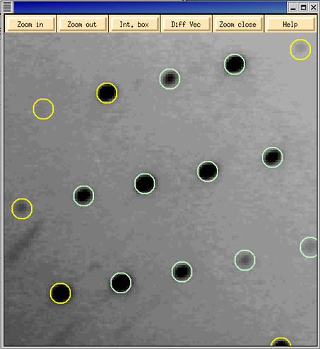
Figure 55. The Zoom window with image after auto-indexing
|
HKL-2000 Online Manual |
||
|
Previous Display Data and Peak Search |
Table of Contents | |