
Length of air or helium, in mm, over which the scattered X-rays are attenuated by a factor of e (2.718).
| format | AIR ABSORPTION LENGTH value_(mm) |
| default | AIR ABSORPTION LENGTH 860 |
| example | AIR ABSORPTION LENGTH 200 [for 2.5 Å X-rays] |
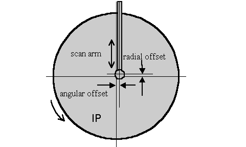
This is one part of the alignment correction needed for the spiral MacScience and MAR scanners. It is the distance, in mm, that the reading head is offset in the non-radial scanning direction from the center of the imaging plate. See also RADIAL OFFSET.
| format | ANGULAR OFFSET value_(mm) |
| default | ANGULAR OFFSET 0.0 |
| example | ANGULAR OFFSET 1.2 |
Defines the shape and size of the background area where the background measurement takes place. Usually defined to be outside of the spot area. However, when no background is specified, the default area is the area just outside of the spot border.
| modifiers | radius | defines the background to be circular with a radius value, in mm. The center of the background area and of the box coincide. |
| elliptical | defines the background to be ellipsoidal with characteristic major and minor semi-axis lengths (in mm), along with the clockwise angle between a horizontal line and the major semi-axis. Refer to the diagram under the keyword SPOT. | |
| formats | BACKGROUND radius value_(mm) | |
| BACKGROUND elliptical value-major_(mm) value-minor_(mm) value-angle_(degrees) | ||
| default | a ring just outside of the spot border | |
| examples | BACKGROUND radius 0.45 | |
| BACKGROUND elliptical 0.80 0.70 0.0 | ||
The value in the image file which does not represent a measurement. Typically 0. When set to 40000 it disables 0. Used only on DIP series scanners to process small molecule data.
Defines the size of the box where both the spot and the background are measured, given as two lengths, in mm. If the BOX size is larger than the average separation between spots (i.e. the boxes overlap), then the program will be slowed down by the spot overlap calculation. The current limit on the box size is 90 pixels in each direction, for a total of 8100 pixels.
The box size can alternatively be specified by the IBOX , where the size is given in pixels instead of mm.
| modifier | tells the program to print the spot definition at the beginning of every refinement cycle (i.e. for every GO statement) | |
| formats | BOX value1_(mm) [slow scan direction] value2_(mm) [fast scan direction] | |
| BOX print value1 value2 | ||
| default | none | |
| example | BOX 2.4 2.4 | |
This command tells the program that it is the last cycle, when the spot intensities are calculated and written to the film output file. It is followed by the command GO . After the cycle both the RAW DATA FILE and the FILM OUTPUT FILE are closed. Signals the SECTOR argument to be incremented by 1.
Defines the orientation and the shape of the detector, historically, a film cassette.
| modifier | rotz,roty,rotx | the three angular deviations from zero |
| radius |
radius of the film in a curved cassette Radius of curvature does not have to be equal to the film-to-crystal distance, and may be different than the radius of the cassette due to the thickness of the film or imaging plate. |
|
| flat | turns off radius | |
| formats | CASSETTE rotx value1 roty value2 rotz value3_(degrees) | |
| CASSETTE radius value1_(mm) | ||
| default | all angles = 0.0 | |
| example | CASSETTE rotx 2.0 roty -1.0 | |
You rarely have to enter these values since the program can refine them once the crystal parameters are established. However, some computer time can be saved if previously determined values are used. Usually they change significantly only after the camera is realigned. There is no limit on values.
The cassette rotations are the primary means by which a non-zero 2q angle is specified (along with DISTANCE , X BEAM and Y BEAM ). For example, a 2q setting of, say, +20 degrees (R-Axis convention), would be described by rotx -20.0 (note change in sign). The will have to be changed as well, since it is the distance from the crystal to the point where it intersects the IP surface. This can be calculated by the formula: Distance (Denzo) = distance (R-Axis) / cos(2q). are the position of the direct beam on the IP during exposure, not at 2q = 0. For large values of 2 q the may be off the detector. The correct value may be negative or more than 200 in such cases.
Alias for the keyword UNIT CELL
This value reflects how fast the detector moves during exposure for Weissenberg images. Given as mm per degree. This is the inverse of the Photon Factory parameter degree/mm, and is only useful for Weissenberg images.
| format | COUPLING value_(mm/degree) |
| default | 0.0 |
| example | COUPLING 0.057 |
Crossfire is a measure of the X-ray beam divergence and focusing as it leaves the collimator and illuminates the crystal. Crossfire, being a symmetric tensor, has x, y, and xy components. It affects the prediction of partial reflections and their positions, not their angular width. It is expressed as angular divergence of the beam. The default value is zero crossfire, i.e. a perfectly parallel beam or a beam focused on the detector.
| modifiers | x | angular spread of the beam in the x direction |
| y | angular spread of the beam in the y direction | |
| xy | correlated xy component of the beam spread. This tends to be zero within error. | |
| format |
CROSSFIRE CROSSFIRE y value2_(arbitrary_units) CROSSFIRE xy value3_(arbitrary_units)
|
|
| defaults | 0 0 0 | |
| example |
CROSSFIRE x 0.023 CROSSFIRE y 0.345 CROSSFIRE xy 0.0004
|
|
| CROSSFIRE x 0.023 y 0.345 xy 0.0004 | ||
Defines the crystal orientation for the calculation of predicted spots.
| modifiers | rotz, roty, rotx | the three angular deviations from the reference orientation specified by andVERTICAL AXIS. See the diagram and further description in Denzo orientation conventions. |
| format | CRYSTAL rotz value1 roty value2 rotx value3_(degrees) | |
| defaults | 0 0 0 | |
| example | CRYSTAL rotx 2.34 roty -4.566 rotz 34.560 | |
The distance from the crystal to the beam spot on the film, in mm, along the X-ray beam path, regardless of the 2q angle (beam to detector axis).
| format | DISTANCE | value_(mm) |
| default | DISTANCE | 75.0 |
| example | DISTANCE | 155.453 |
EIGENVALUE FILTER (USE IT WITH GREAT CAUTION)
When attempting to simultaneously refine two or more highly correlated parameters with Denzo, an eigenvalue filter is triggered and an error message appears in the log file stating that the parameters being fit were too highly correlated to be fit simultaneously. The eigenvalue filter value provides a way of defeating this check, by lowering the value. Unfortunately, just because you change the value doesn't mean that the correlated parameters are going to become uncorrelated, so changing the value is unlikely to help you and may lead to some horrible result.
| format | EIGENVALUE FILTER value |
| default | 0.001 |
| example | EIGENVALUE FILTER 0.0005 |
Signals the end of the Denzo job. Placed at the end of the command file or used to exit from Denzo during manual fitting and indexing.
END OF PACK (REDUNDANT)
Signals the SECTOR argument to be incremented by 1. The CALCULATE GO statement does now the previous work of END OF PACK.
The keyword ERROR and its modifiers defines the model for the error in the measurement of the spot positions. The default values should be adequate in most cases and you should not worry too much about them. The error model does, however, directly affect the c2 values printed out at the end of each cycle of refinement. Since this is usually the only check you can reasonably make as to the success of your data reduction in Denzo, it is wise to know something about how these are calculated. The names of the modifiers contributing to the error definition should not necessarily be taken literally, since they are short hand notation for complicated effects on the accuracy of the measurement. The model has been developed and black boxed (i.e. given the Z.O. Good Housekeeping seal of approval) to give a realistic estimate of the weight each spot should contribute to the refinement of the crystal and camera coordinates. This model gives c2values close to one for good (non-mosaic) crystals. For mosaic crystals either error positional needs to be increased or higher values than 1 of c2 should be expected.
| modifiers | positional |
The minimum error, in mm, in the positional measurement. It is usually a fraction of the pixel size, typically one half or one quarter of a pixel. Its squared value is added to the other components of the error estimate. Enlarging this value will lower your c2values, but will not necessarily improve your data. If you have to increase this value much for a well-tested instrument like MacScience or R-axis, check the instrument alignment.
|
| density |
Models the error measurement of the optical density of the film. The error equals the square root of the corrected reading times the density value. This is used only to estimate the error in spot positions and in the definition of strong reflections. The error density is affected by the voltage on the photomultiplier. The higher the voltage, the higher the error density, with a very steep dependence.
|
|
| overload | Refers to the increase in the modeled positional error due to the existence of pixels with intensity overflow. For every overflowed pixel the modeled error squared is increased by the overload value squared. | |
| y/x factor | This reflects the increase in the positional error of the spot due to its being close to the oscillation axis. The error estimate is by 1 + the ratio of y/x factor to the absolute value of the tangent of the angle between the oscillation axis and the line connecting the spot with the beam spot. This prevents the spot distortion which occurs close to the oscillation axis from affecting the refinement very much. | |
| partiality | The expected error of the partiality determination The value for the error is expressed as a decimal, e.g. ±10% would be written 0.1. | |
| systematic | The weight given the positional refinement compared to the partiality refinement when refining crystal orientation parameters. The higher the value, the more weight is given to the positional refinement. Typical values range from 1 to 20. A value of 5 seems to work almost all the time. | |
| format | ERROR modifier1 value modifier2 value ... | |
| defaults | overload 0.005 | |
| density detector and wavelength dependent | ||
| positional 0.030 | ||
| y/x factor 0.1 | ||
| partiality 0.10 | ||
| systematic 5.0 | ||
| example | ERROR systematic 5.00 partiality 0.100 positional 0.050 | |
Avoid modifying the error parameters other than positional and density. Moreover, error density should be constant for a detector (site) and changed only with caution.
Defines the position of the fiducial marks on the film relative to the beam spot, before FILM rotation and Y SCALE are applied. Given as a series of x,y coordinates, in mm. These days this is only used with Photon Factory Weissenberg images.
| format | FIDUCIALS xvalue_(mm) yvalue_(mm) xvalue_(mm) yvalue_(mm) ... |
| default | none |
| example | FIDUCIALS -90.0 -90.0 90.0 -90.0 |
This keyword tells the program about the characteristics of the data collection medium. Identical to the keyword IMAGING PLATE .
| modifiers | absorption | Total absorption of the film. Default is 100 for image plates |
| length | Distance from the top of the detector to the last useful pixel in the fastdirection. Depending on the detector, on the computer display it could be the apparent width of the detector. | |
| width | Width of the detector in the slow direction. Depending on the detector, on the computer display it could be the apparent height of the detector. | |
| rotation |
Describes the orientation of the spindle relative to the detector. The value of the FILM rotation is function of which file storage convention (see figure 5 in Detector Conventions analysis) is being used.
For manual scanner, adding 180 to film rotation can compensate for putting plate upside-down into scanner. Small changes (refined by Denzo) to film rotation can compensate for small rotation slop that is inherent when manually handling plates. |
|
| output file | This gives the name of the processed output file | |
| formats | FILM modifier1 value ... | |
| output file format is a string of characters | ||
| defaults | absorption 100 | |
| length detector dependent | ||
| rotation detector dependent | ||
| output file (none) | ||
| examples | FILM rotation 270.0 | |
| FILM absorption 2 | ||
These command words tell the program to FIT (refine) or FIX (not refine) a parameter specified by a Denzo keyword. The FIT command is followed by the command GO, which calls one cycle of refinement. One GO command calls one cycle of refinement, 5 GOcommands call for 5 cycles of refinement, etc. If a keyword parameter is fixed, it will retain its current value through the refinement. The program assumes that all of the keyword parameters are fixed at the beginning of every new frame.
The effect of these commands is cumulative and carries over through subsequent cycles of refinement. For example, if the command FIT CRYSTAL rotx roty rotz GO is given, then on every subsequent refinement cycle (called by the GOstatement), the CRYSTAL rotx roty and rotz parameters will be refined. Typically a refinement starts by fitting just a few parameters, like CRYSTAL rotx roty rotz, allowing the refinement to proceed towards convergence for a few cycles, and then fitting more parameters a few at a time. The keyworded parameters that can be FIT are given below.
All of the keyworded parameters can be refined simultaneously, so care should be taken not to fit parameters which are too strongly correlated at low resolution. For example, the crystal to film distance and the unit cell lengths are highly correlated, so one should be allowed to refine before refining the other (usually the unit cell lengths are refined first).
The and END FIX command words mark the end of a list of fitted parameters. This is especially useful for inputing more parameters after you have called a FIT command.
Consider the following case: you want to refine the crystal rotation values, so you type rotx roty rotz. Now let's say that you also want to enter a new value for the distance before giving a GO command. You might think to try FIT CRYSTAL rotx roty rotz DISTANCE 200 GO, but this won't work! Program will not recognize the 200, and it will give you an error message, plus it will try to refine the distance value as well. The solution is to use the END FIT rotx END FIT DISTANCE 200 GO.
The option FIT cell ,when used in conjunction with the SPACE GROUP or LATTICE. The option FIT cell ,when used in conjunction with the SPACE GROUP or LATTICE command, tells the program to fit the unit cell lengths and angles. The program is smart enough to know which lengths and angles are to be fit, and which are to be fixed. For example, it knows enough to keep all angles at 90 degrees in orthorhombic space group. Likewise, it also knows enough to keep a= b in tetragonal space groups, etc. The LATTICE or SPACE GROUP must be declared before FIT CELL can be used.
In practice most often option used is FIT all .This will fit all parameters that can be sensibly fit given the circumstances (space group, detector). Fitting all parameters is now stable even at low resolution.
| FIT- and FIX - able keywords | all, a*, b*, c*, alpha*, beta*, gamma*, cell, CRYSTAL rotz rotx roty,CASSETTE rotz rotx roty, radius, DISTANCE, X BEAM, Y BEAM, Y SCALE, SKEW,FILM rotation, CROSSFIRE x, y, xy |
| format | FIT KEYWORD modifier |
| default | all keyword parameters fixed (i.e. type GO and nothing will be refined) |
| examples | FIT CRYSTAL rotx roty rotz |
| FIT X BEAM Y BEAM Y SCALE SKEW DISTANCE GO GO GO |
Do not run alternative cycles of fit and fix commands! This is the old way and does not take advantage of the fact that the Denzo refinement is very stable and can refine many parameters simultaneously. Simultaneous refinement is the best way to avoid getting into a false minima.
A critical keyword. The modifier following this keyword tells the program about a series of defaults to use for the detector parameters. This keyword can thus substitute for many of the parameters called by, for example, the FILM (orIMAGING PLATE) keyword.
A detailed table of all the keywords specified by the format keyword can be found in the Defaults Values and Detector Specific Information appendixes.
| modifiers | see Detector Specific Information appendix |
| format | FORMAT modifier |
| default | this is a required input! |
| example | FORMAT dip2000 |
This command tells the program to execute one iteration cycle of refinement. After the cycle the fitted parameters will have new values. You can specify more than one in one line. This will tell Denzo to print results of the fit only for the last cycle from the series of GOs. See also FIT/FIX .
IBOX (REDUNDANT)
IBOX is exactly the same as the keyword BOX , except that instead of giving the dimensions of the box in mm, the dimensions of the box are given in pixels. The I in IBOX stands for integer. The maximum dimensions of the box are 90 pixels in each direction.
| format | IBOX integer integer_(pixels) |
| default | none |
| example | IBOX 25 25 |
Tells the program to ignore a specific region of the X-ray image. For example, this is useful for excluding the shadow due to the beam stop. Don't try to use this for masking out ice rings. That is accomplished using the REJECT fractionkeyword. It is useful to think of IGNORE as describing a masked-out area of the film. The mask is provided by a series of geometrical descriptions, followed by their coordinates. For example, the beam stop shadow could be masked out by a combination of a quadrilateral and a circle (i.e. a lollipop shape).
| modifiers | quadrilateral | A quadrilateral as defined by four x,y coordinates, in mm, picked in acounterclockwise (if Y SCALE > 0) or clockwise (if Y SCALE < 0) direction. The best way to do this is to use the cursor to pick the points off of the display window. The x, y coordinates in mm are listed in the bottom row of the green box of the display. | |
| circle | defined by the x,y coordinates of the center, and the radius of the circle, all in mm. | ||
| triangle | defined by three x,y coordinates. Use the display program to pick these. | ||
| format | IGNORE | quadrilateral x1 y1 x2 y2 x3 y3 x4 y4 (all values in mm) | |
| circle x5_(mm) y5_(mm) r_(mm) | |||
| triangle x6 y6 x7 y7 x8 y8 (all values in mm) | |||
| default | nothing ignored | ||
| example | IGNORE quadrilateral 50 0 52 0 52 100 50 100 | ||
IMAGING PLATE (REDUNDANT)
This substitutes 1 for 1 with the keyword FILM.
This keyword is the same as the @ keyword. Signals to the program to change reading of the control data to an auxiliary file. At the beginning of the program the auxiliary file is closed, so the keyword INPUT has to be followed by the filename of the auxiliary file. The auxiliary file is read until a semicolon is reached (or an end of file mark is detected). The control is then returned to the original input stream. In the case of reaching a semicolon, the auxiliary file remains open, and the next time the keyword INPUTappears it must not be followed by a file name or else the program will become confused, since it still wants to read from the open auxiliary file. On the other hand, if control is returned due to an end of file mark, then the next time input is encountered it must have an auxiliary file name next to it. If you give it the same auxiliary file name as before, then it will begin reading the auxiliary file from the beginning. Nesting of auxiliary files is not allowed. Auxiliary files are useful to keep the data common to many films in a separate file.
| format | INPUT filename |
| default | none |
| examples | INPUT subbatch1.dat |
| @ refine |
Sets the number of reflections in a resolution shell used to define that resolution shell for the purpose of refining partiality. Default is 100.
LAMBDA (REDUNDANT)
X-ray wavelength. Same as keyword WAVELENGTH.
| format | wavelength in Ångstroms |
| default | 1.5418 [Cu Ka] |
| example | LAMBDA 1.5418 |
LATTICE (REDUNDANT)
Lattice type. Note that this command is superseded by the SPACE GROUP command for most routine use.
| format | single letter or single letter with name. Can also specify lattice type. Possible choices are: P, C, A, B, F, I and R |
| default | P triclinic |
| example | LATTICE P monoclinic |
The left margin, in mm from the left edge, of useful data. It is defined in the raw data convention, not in the display program convention.
| format | LEFT MARGIN value_(mm) |
| default | 0.0 |
| example | LEFT MARGIN 2.0 |
This command is normally used in the manual mode. It tells the program to provide a list of the current parameters. This is convenient if you forget where you were in the refinement, or you want to copy down the latest parameters. To use, just type LIST .
In the autoindexing subroutine of Denzo, LONGEST VECTOR denotes the longest real-space vector, in Å, the program expects to find in the reduced, primitive, unit cell. If the autoindexing fails, and you are confident of your X BEAM , Y BEAMand DISTANCE values, then this is the next parameter to try changing. Typically you would either input a value close to or somewhat larger (say 50%) than what you really suspect is the longest vector in the unit cell.
| format | LONGEST VECTOR value_(Å) |
| default |
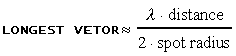 |
| example | LONGEST VECTOR 300 |
Defines the polarization of the X-ray beam. Same as the keyword POLARIZATION. This correction is not a big deal except for synchrotron radiation, where it is a minor deal unless you are collecting high angle data. The Denzo definition of polarization is as follows:

where Is is the intensity of the electric field squared of the X-ray beam along the spindle axis, and Ip is the intensity perpendicular to the spindle axis. Values range from +1.0 to -1.0.
Generally speaking, this is not a number you can measure very easily, and is often calculated theoretically. It is really the responsibility of beam line operators to know this value for their beam lines. Note that the sign of the correction depends on whether the spindle is horizontal or vertical. As a rule of thumb, if the polarization correction is > 0, then the intensity of the X-ray scattering is stronger perpendicular to the axis of the spindle than it is to the axis parallel to the spindle. You can check the background of your image to confirm this. Typical values range from ± 0.11 for graphite to + 0.9 for synchrotron beams (the spindle axis is typically oriented at synchrotrons to make the polarization positive). For a laboratory source, use modifiers: graphite (if graphite monochromator is installed) or filter (if X-ray beam is filtered or mirrors are installed).
| modifiers | filter | No polarization, value = 0 |
| graphite | Reflecting plane perpendicular to the plane formed by the spindle and the beam, CuKa and MoKa radiation. Value of ±0.11 for CuKa or ±0.03 for MoKa. | |
| format | MONOCHROMATOR modifier | |
| default | 0.0 | |
| example | MONOCHROMATOR graphite | |
| POLARIZATION -0.11 | ||
The old keyworded values for the synchrotrons are probably wrong now. Always ask the synchrotron staff what the correct number is. A good guess for a bending magnet source is polarization 0.9. For a wiggler source it can vary a lot from station to station, in the range of 0.0 to 0.9.
Defined in Denzo as the rocking angle, in degrees, in both the vertical and the horizontal directions which would generate all the spots seen on a still diffraction photograph. It includes contributions due to X-ray bandwidth, beam crossfire, etc.
| format | MOSAICITY value_(degrees) |
| default | this is a required input! |
| example | MOSAICITY 0.5 |
Tells the program not to use the beam spot in the refinement. If the option USE BEAM has been invoked earlier in the refinement, it should be revoked with the NO BEAM keyword in the later stages.
| format | NO BEAM |
| default | this is the default option. see USE BEAM |
Specifies the size of the data file. Equal to the number of vertical (fast scanning direction) lines. The default value is now 'hard wired' into the FORMAT modifier. In other words, once you specify the detector, the NUMBER OF RECORDS value is input from a look-up table.
| format | NUMBER OF RECORDS integer |
| default | comes along with whatever FORMAT is specified |
Defines the area outside a specified circle or ellipse, but within the box, to be omitted from any use. By default there is no omitted area.
| modifiers | radius or rad | Defines the omit boundary to be circular with a radius value, in mm. The center of the omit boundary and that of the box coincide |
| elliptical orell | Defines the omit boundary to be ellipsoidal with characteristic major and minor semi-axis lengths (in mm), along with the clockwise angle between a horizontal line and the major semi-axis. Refer to the diagram under the keyword SPOT. | |
| formats | OMIT radius value | |
| OMIT elliptical valuemajor valueminor valueangle | ||
| default | no area omitted | |
| examples | OMIT rad 0.35 | |
| OMIT ell 0.70 0.60 0.0 | ||
This keyword tells the program that the oscillation method is being used.
| modifiers | start | Starting oscillation angle |
| end | Ending oscillation angle | |
| step | Angle between 1st oscillation start and 2nd oscillation start | |
| range | The actual oscillation angle | |
| formats | OSCILLATION modifier1 value1_(degrees) modifier2 value2_(degrees) ... | |
| default | end = start + range | |
| step = range | ||
| examples | OSCILLATION range 1.0 start 30.0 | |
| OSCILLATION start 30.0 end 31.0 | ||
| OSCILLATION range 1.0 step 0.8 start 30.0 | ||
| the first two examples describe the same thing. The third describes a series of 1 degree oscillations with ranges which overlap by 0.2 degrees. | ||
Overlap defines which pixels of any spot are checked for overlap with the pixels of a neighboring reflection box. The choices are the spot pixels, the guard pixels (found between the spot circle and the background circle) or none. For example, if you specify OVERLAP spot and if the spot pixels overlap with the spot pixels of another reflection, then the two reflections are flagged as overlaps.
| modifiers | spot |
| guard | |
| none | |
| format | OVERLAP modifier |
| default | none |
| example | OVERLAP spot |
The lowest optical density reading considered unreliable due to saturation of the film or image plate. The default value corresponds to the full dynamic range being useful with only the highest value being considered overflow. A value that is higher than the maximum possible in the data tells the program to ignore the intensity overflow. The range of the values themselves are determined by the analog to digital converter used to write the data. For 8-bit ADC's (found on film scanners) the highest value is 28-1 =255. For the 16-bit ADC's found on most on-line detectors the range is from 1 to 216-1 = 65535. The particular OVERLOAD VALUE that is considered unreliable has been determined for several detectors and is input as the default when you specify the detector using the FORMAT keyword. Denzo applies the overload table in Mar scanners so that the overload value should represent the highest reliable entry in the Mar overload table.
| format | OVERLOAD VALUE integer (units are function of detector type) |
| default | separate values for different IP formats, contained in FORMAT defaults |
| example | OVERLOAD VALUE 255(film) |
One-of-a-kind detectors as well as the very old Mar scanners may have the wrong default value.
The overload value is a data representation value before applying the data format dependent correction for strong intensities.
Default values assume the full dynamic range of the instruments (Mac Science, Mar, R-Axis).
PEAK SEARCH FILE peaks.file
Tells the program to perform autoindexing. Get slightly confused?
PLATE ROTATION (REDUNDANT)
This is exactly the same as the keyword FILM rotation. I recommend you stick with FILM rotation, to avoid getting confused with too many aliases.
POLARIZATION (REDUNDANT)
Same as MONOCHROMATOR.
The PRINT command tells the program to print the output specified by subsequent keywords to the log file. It does not affect the results of the refinement. Default values of the print sub options can be of several types. Some options are printed by default at every cycle, some are printed on the last cycle of every film of the refinement, and some are never used unless specified. See specifically the various print descriptions below.
| modifiers | chi square |
print the c2 statistics, including the number of spots fitted, the c2 of x and y (a measure of how well the spots were fitted based on what sort of error you expected - see alsoERROR), and the predicted decrease in the c2s after the current cycle of refinement.
For those of you who just want numbers, c2's should be close to 1.0 (between 0.5 and 2.0), and the predicted decrease should be near zero, showing that the refinement has converged. |
| fitted | Print to the log file the observed and fitted profiles of those spots having the specifiedhkl value. No density readings in the background will be printed. By default, no fitted spots printed. | |
| hkl | Print to the log file the density readings and other statistics of those spots having the specified hkl value. By default, no hkls printed. | |
| memory | Print statistics of the usage of variables. | |
| profiles |
The profiles modifier tells the program to print the average spot profile in a specified number of regions to the log file.
It is best to refrain from printing profiles until the very last cycle of refinement or else your log file will become truly gargantuan. You can also specify PRINT no profilesat the beginning of your refinement, just to make sure it is off until you want to turn iton. |
|
| shifts | PRINT shifts tells the program to print the value, the change from the previous value, and the estimated error of all the keyworded parameters fitted on a current cycle of refinement. PRINT no shifts turns this off. | |
| solver | This little-used command prints out correlation matrices calculated in the refinement. | |
| statistics | Print the hkl statistics, including the number of whole and partially recorded reflections matched with preds. | |
| zones |
Print out a list of equivalent zones, given as alternative values for CRYSTAL rotx roty and rotz. One advantage to invoking this option is to use rotx, roty and rotz values that are more convenient to remember or type. For example, instead of using crystal rot values of, say, -213.6, 137.4, -13.27, you could use the equivalent values of, say, (I'm just making these up) 18.2, -15.4, 63.9. If you wanted to orient your crystal for a particular data collection scheme, these alternative zones could make life easier. PRINT zones lists all of these equivalent values.
|
|
| format |
PRINT chi square / no chi square |
|
|
PRINT fitted integer integer integer |
||
|
PRINT hkl integer integer integer |
||
|
PRINT memory /no memory |
||
|
PRINT profiles integer integer (the first integer specifies the number of equal sized horizontal regions to divide the frame into, the second specifies the number of equal sized vertical regions. The total number of regions is the product of the first and second integers) / PRINT no profiles |
||
|
|
||
|
PRINT solver / no solver |
||
|
PRINT statistics / no statistics |
||
| defaults | chi squares printed after every cycle of refinement | |
| no fitted spots printed | ||
| no hkls PRINT | ||
| print memory statistics on the last cycle | ||
| no profiles printed except on the last cycle, when a 3 x 3 grid is printed | ||
| all shifts printed | ||
| no solver | ||
| statistics | ||
| examples |
PRINT fitted 12 8 0 |
|
|
PRINT profiles 3 3 (tells the program to divide the frame into 9 equal regions and print out 9 average spot profiles). the more profiles you specify, the larger the log file will be |
||
|
PRINT hkl 12 8 0 |
||
You can easily generate gigabytes of log file if you use some of the print options, so be careful!
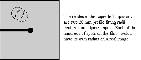
The radius of the area around each particular spot, in mm, containing neighboring spots, used to calculate the average spot profile. The spot in question is fitted to the average profile of all the spots within the specified radius. Generally, the radius is set so that spots on roughly 3-5% of the area of the detector are included in the averaging. Only on the last cycle of the refinement is the profile fitting applied, via the keyword CALCULATE .
The particular size of the area chosen depends on how much the profiles vary across the film and the density of the spots on the film. For example, if the spot profiles vary a lot across the film, then you would choose a smaller radius. If you have a small lattice and the spots are widely separated, you might want to choose a larger radius.
The calculation of the average profile is a time consuming task, proportional to the number of spots in the profile fitting radius circle, but too small a radius will not capture enough spots and lead to a noisy average profile. Too large a radius will average out significant profile variations.
To see the PROFILE FITTING RADIUS in ImageWindow of XdisplayF click  . A thin white circle corresponding to the profile fitting radius will appear and will move around with the cursor; only those spots whose intensity is above the weak level will have predictions displayed in this mode and only these reflections are used in the calculation of the average spot profile (to return to the normal mode, click again).
A good rule of thumb is that the PROFILE FITTING RADIUS should enclose about 10 to 50 spots whose intensities are above the weak level. Useful increments of the profile fitting radius are 2.5% of the detector size (e.g. 5 mm for a 200 mm wide IP).
| format | PROFILE FITTING RADIUS value_(mm) |
| default | 20.0 |
| example | PROFILE FITTING RADIUS 30.0 |
Exit from program Denzo. Same as STOP or a semicolon (; ).
This is one part of the alignment corrections needed for the spiral MacScience and MAR scanners. It is the radial departure, in mm, of the scanning heads from perfect concentricity with the imaging plate. A perfectly aligned scanner would have a RADIAL OFFSET of 0.0. The radial offset is perpendicular to the angular offset. A diagram of these offsets is shown under the ANGULAR OFFSET keyword.
| format | RADIAL OFFSET value_(mm) |
| default | 0.0 |
| example | RADIAL OFFSET -0.43. |
Pixel size in the horizontal (slow scanning) dimension
| format | real number in mm |
| default | defined by the values in the FORMAT statement |
| example | RASTER 0.1 |
This defines the detector data file name template. If the file name contains a run of # characters, then they will be substituted with the numerical value of the SECTOR argument. This allows for easy processing of a large series of sequential images.
| format | RAW DATA FILE file_name |
| default | none |
| examples | RAW DATA FILE 'bigdisk:[dir.frames]xtal001.osc' |
| RAW DATA FILE /vms/data/dir/xtal###.osc | |
| in the first example the single quotes are necessary, or else the directory names in square brackets will be ignored (commented out). |
You must not repeat this command before the next GO statement.
Defines the number of pixels in the data record. It is equal to the number of horizontal (slow scanning direction) pixels.
| format | RECORD LENGTH value_(pixels) |
| default | FILM length / (RASTER / Y SCALE ) (this is defined by the FORMAT statement) |
| example | RECORD LENGTH 2000 |
REFINE PARTIALITY / REFINE NO PARTIALITY (DO NOT USE!)
Tells the program to determine the fraction partiality of the reflections on the image. It is critical that this be on during the refinement of the crystal rotation parameters, since CRYSTAL rotx and roty cannot be determined without knowing the partiality of the reflections on the image.
| format | REFINE PARTIALITY |
| default | REFINE PARTIALITY |
Do not use REFINE NO PARTIALITY ! (see theoretical explanation in Refinement: Using the Fit Command chapter in Manual).
Describes a condition whereby a reflection is rejected by Denzo. This is especially useful for eliminating spurious measurements due to ice rings.
| modifiers | fraction | The fraction of acceptable pixels in the background, which are needed for the reflection to be accepted. Default = 0.75 (i.e. 75%). Very sensitive to small changes, so increment by 1-2% if you are messing with this. To get rid of spots in an ice ring, increase this value by 1-2% until the preds in the ice ring are colored red. After all, the defining feature of an ice ring is a horrible background. The acceptability of a background pixel is determined by the next three modifier words. |
| cutoff |
The s deviation from the best fit to the background plane at which a pixel has a 50% chance of being incorrect and thus rejected. Default is 3s.
The background of a spot can be described by a plane and should be uniform and flat. Sometimes it is not; for example, it may have a slope to it, which can be calculated. If a pixel is still out of the best-fit background plane by (default) 3, then it is flagged as a reject. It is best not to mess with this unless you really know what you are doing. |
|
| slope | The slope of the background plane above which the entire background and spot are considered unacceptable and rejected. Default is 50 units. Flat = 0, vertical = infinite. It is sometimes useful to increase this to 100 for very low background images. | |
| systematic | This is a way of changing the background rejection criteria when you have a major problem with diffuse scattering. Default is 0.01. The range is from 0 to 1, with 0 meaning rely totally on the cutoff criteria, and 1 meaning don't reject anything. As you can see from the default, you normally use the 3s cutoff criterion. | |
| format | REJECT fraction value | |
| defaults | REJECT fraction 0.75 | |
| REJECT cutoff 3.0 | ||
| REJECT slope 50 | ||
| REJECT systematic 0.01 | ||
| example | REJECT fraction 0.80 | |
RESOLUTION LIMITS / RES
Defines the resolution range used in the program, in Ångstroms.
| format | RESOLUTION LIMITS valuelower valueupper_(Å) |
| default | none |
| example | RESOLUTION LIMITS 20.0 2.5 |
| RES> 20.0 2.5 |
This is the counter and range delimiter for a series of frames when processing in batch mode. The number in the sector argument is substituted for the ### (or #, or ##, ...) variable in the RAW DATA FILE and FILM output file commands. Make sure there are enough # marks to accommodate all of the digits in the sector argument, e.g. if you have sector values in the 100's then there must be at least three # marks in the file names specified in RAW DATA FILE and FILM output file . The sector value can start at any non-negative integer, and is incremented by 1 every time an END OF PACK statement is reached. The first number in the sector argument is the first frame and the last number is the last frame. See also START REFINEMENT.
| format | SECTOR integer to integer |
| default | none |
| example | SECTOR 1 to 50 |
SKEW refers to the non-orthogonality of the vertical and horizontal scanning directions, measured in radians. For a perfectly orthogonal system SKEW is defined to be zero. Generally SKEW values will be very close to this number. It can be fitted in the later rounds of parameter refinement.
| format | SKEW value_(dimensionless) |
| default | 0.0000 |
| example | SKEW 0.00169 (value taken from the earlier refinement) |
Spiral scanners and CCD detectors should use the default value of zero, which should not be refined.
The space group symbol or number as given in the International Tables. Note that for rhombohedral space groups autoindexing only works for the primitive choice, i.e. H3 or H32, not R3 or R32. The must be declared before the FITCELL command can work.
Denzo does not actually care about the SPACE GROUP per se. It indexes films by Bravais lattice and does not take into account systematic absences arising from two-folds, screws, etc. These are accounted for in Scalepack, when the data are reduced. So for the purposes of Denzo, the resulting .x file will be the same whether you declare the space group to be P222 or P212121, or, P3 and P6122.
| format | SPACE GROUP modifier |
| default | P1 |
| example |
SPACE GROUP P212121 |
SPINDLE AXIS / ORIENTATION AXIS 1
The reciprocal lattice vector parallel to the spindle axis. Same as Scalepack keyword ORIENTATION AXIS 1
| format | 3 integers representing the reciprocal vector |
| default | 0 0 1 (c* axis) |
| example | SPINDLE AXIS 1 0 0 (a* axis) |
| SPINDLE AXIS 1 0 1 (a non-major axis) |
Defines the shape and area of the region in the box where the spot is to be found.
| modifiers | radius | Defines the spot to be circular with a radius value, in mm. The center of the spot area and of the box coincide |
| elliptical | Defines the spot to be ellipsoidal with characteristic major and minor semi-axis lengths (in mm), along with the clockwise angle between a horizontal line and the major semi-axis. | |
| formats | SPOT radius value_(mm) | |
| SPOT elliptical valuemajor valueminor_(mm) valueangle_(degrees) | ||
| defaults | none | |
| examples | SPOT radius 0.35 | |
|
SPOT elliptical 0.70 0.60 0.0
See diagram (fig. 4) in Mosaicity and Spot Shape section in Manual |
||
START REFINEMENT denotes the start of the series of commands given to index the diffraction image. The end of the loop is denoted by the CALCULATE GO statement. The statement must come after the SECTOR x to y
| format | |
|
|
|
| default | |
| this is not a default | |
| example | see the example command file in Finishing Up section |
STOP (REDUNDANT)
This command stops the Denzo job. Same as QUIT or a semicolon (;).
SWAP BYTES (OBSOLETE)
All HKL programs now automatically recognizes swapped data.
Data set title
| format | string. If it contains any spaces, commas, equal signs, or brackets (Denzo-recognized separators), it must be enclosed in single quotes. |
| default | none |
| example | TITLE 'my crystal' |
The top margin, in mm from the top edge, of useful data, i.e. the beginning of every record. Do not set the top margin to be larger than the film length. Note that commands like top margin are working in the data coordinate system. It is very important to check the results of these commands in the display window.
| format | TOP MARGIN value_(mm) |
| default | 0.0 |
| example | TOP MARGIN 2.0 |
Unit cell parameters in either real or reciprocal space.
| format | UNIT CELL a* b* c* a* b* g* or UNIT CELL a b c a b g. Lengths in Ångstroms or reciprocal Å, angles in degrees. |
| default | none |
| example | UNIT CELL 120.92 120.92 131.65 90 90 90 |
If the space group has been declared, the program is smart enough to know which cell lengths should be equivalent, and which angles are variable, and it will hold those lengths equal or fixed throughout the refinement.
Tells the program to use the beam spot in the refinement. This keyword has the opposite effect of the keyword NO BEAM beam. This is useful in the initial steps of the refinement, when not too many spots are matched by preds.
| modifier | only | Tells the program to use only the beam spot in the refinement. Has the effect of turning off the RESOLUTION LIMITS keyword. |
| format | USE BEAM | |
| USE BEAM only | ||
| default | not the default option. See NO BEAM. | |
USE FIDUCIALS / USE NO FIDUCIALS
Tells the program to use the fiducials in the refinement. Turned off with USE NO FIDUCIALS . Fiducial positions are entered with the keyword FIDUCIALS.
| modifier | only | Tells the program to use only the fiducial positions in the refinement. |
| format | USE FIDUCIALS | |
| USE FIDUCIALS only | ||
| default | not the default. Default is USE NO FIDUCIALS. | |
USE PARTIALS POSITION / USE PARTIALS NO POSITION
Normally, data reduction programs use only fully recorded reflections in the refinement of the crystal and detector positional parameters. The keyword USE PARTIALS POSITION tells the program to use a reflection that is predicted to be only partially recorded in the positional refinement. A spot is predicted to be partially recorded based on the values entered for the oscillation range, as well as the crystal mosaicity and beam crossfire. This is a very useful feature of Denzo, because it allows one to refine the orientation of the crystal even if none of the reflections are fully recorded. This occurs if one collects either very thin oscillation sectors (in an attempt to minimize background) or has a crystal of relatively high mosaicity, or some combination of both. USE PARTIALS NO POSITION is mostly of historical interest.
| format | USE PARTIALS POSITIONS |
| examples | USE PARTIALS POSITIONS |
|
USE PARTIALS NO POSITIONS |
VERTICAL AXIS / ORIENTATION AXIS 2
The reciprocal lattice vector perpendicular to both the spindle axis and the X-ray beam. Equivalent to ORIENTATION AXIS 2.
| format | 3 integers representing the reciprocal vector |
| default | 1 0 0 (a* axis) |
| example | VERTICAL AXIS 0 1 0 (b* axis) |
X-ray wavelength. Same as LAMBDA .
| format | WAVELENGTH value_(Ångstroms) |
| default | 1.5418 (CuKa) |
| example | WAVELENGTH 1.5418 |
This is the intensity rejection level, expressed as an I/ ratio. Only strong spots with an integrated intensity (i.e. I) above the WEAK LEVEL times the intensity error measurement (i.e. ) are used in the positional refinement and as reference profiles in profile fitting.
The intensities of all reflections determined to be weak are still measured and included in the .x file. They're just not used in the profile fitting. You can use in the XdisplayF window to see which reflections are above the weak level.
| format | WEAK LEVEL value_(dimensionless) |
| default | 5.0 |
| example |
|
WRITE PREDICTIONS / WRITE NO PREDICTIONS
This tells Denzo to write a file called hkl predictions. This file contains the positions of the predicted reflections, and is read by XdisplayF to update the predictions in the display. Once the flag is turned on, the file is updated every time a new cycle of refinement is executed. This way you can follow the course of the refinement in the display program. Turned off with WRITE NO PREDICTIONS.
| format | WRITE PREDICTIONS |
| default | WRITE PREDICTIONS |
| example | WRITE PREDICTIONS |
Defines the distance from the edge of the data to the beam spot, in mm. You can use coordinates of the cursor in the green box of the XdisplayF window to find the beam position.
| format | X BEAM value_(mm) |
| default | FILM width/2 |
| example | X BEAM 98.961 |
Defines the distance from the edge of the data to the beam spot, in mm. Again, use coordinates of the cursor in the green box of the XdisplayF window to find the beam position.
| format | Y BEAM value_(mm) |
| default | FILM length/2 |
| example | Y BEAM 100.146 |
Y SCALE in Denzo serves two purposes. First, it is a dimensionless correction factor for anisotropy in the pixel dimensions. It is applied to the fast scanning, or y, dimension of the pixel. If the pixel is larger in y than in x, then Y SCALE is smaller than 1.
It is possible to create a data file which has the inverted direction of scanning along one of the axis - similarly as in case of film scanned from back side. Denzo handles this aberration by changing the sign of the Y SCALE keyword to negative. If this is not done, then the assignment of the Friedel mates (Bijvoet differences) will be inverted, and thus the hand of the structure will be similarly inverted - see Determining the values of FILM ROTATION and Y SCALE section in 'Denzo Orientation Conventions' chapter.
The sign of Y SCALE is a detector property, while the absolute value of Y SCALE seems stable for all detectors. Once the correct sign has been determined, the calibration of Y SCALE is done by refining with a high symmetry crystal (trigonal, tetragonal, hexagonal, or cubic).
For CCD and spiral scanners the value of Y SCALE should be exactly ± 1 and not refined !
| format | Y SCALE value_(dimensionless) |
| default | detector dependent, defined by FORMAT statement |
| example | Y SCALE 1.03152 |
Substitutes for the OUTPUT FILE command, and tells the program to write the '.x' file in the Eleanor Dodson York file format. Note that Scalepack reads the Denzo YORK OUTPUT FILE as format denzo_york1.